1B: Power Transmissions
Power Transmissions
In FRC, the three most common types of power transmissions are gears, chain and sprocket, and belt and pulley. Although they all achieve the same end result of changing speed and torque, they each excel in different situations. In the following sections you'll be introduced to each of them and how to model them.
Note
Gears, sprockets, and pulleys all follow profile standards that specify how big the teeth are. This means that the ratio between the number of teeth and diameter of the part is a constant. There are different profile standards, but only parts of the same profile can be meshed or used together.
Gear Basics
Gears are mechanical devices with teeth that mesh with each other to transmit motion or power between rotating shafts. They're like wheels with teeth that fit together, allowing them to transfer torque, change speed, and change direction of rotation.

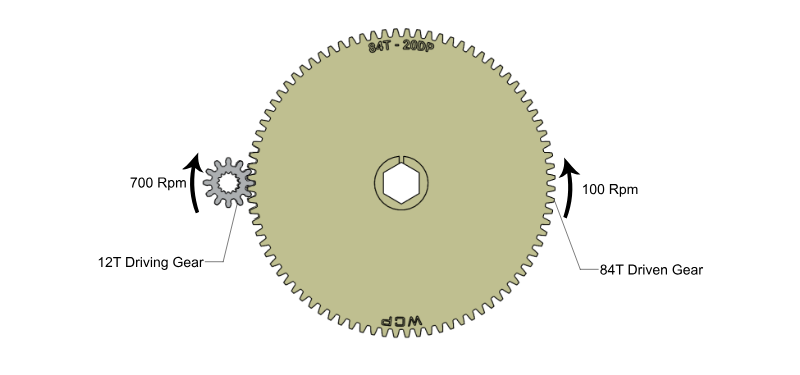
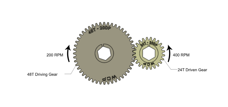
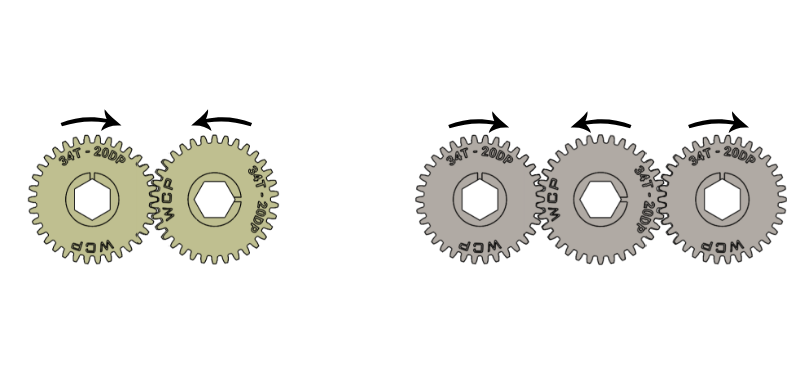
In order to change the torque and speed from the input to output, different sized gears must be used. Remember that the ratio is related to the number of teeth of the gears. Teeth will always mesh together one by one, but the number of teeth per revolution is different for different sized gears, causing a difference in angular speed even if the surface speed of the gear is the same. Click through the following slides to see a visualization of different gear ratios.
Center to Center Calculation
To calculate how far apart to space the gears, you can use the following formula to calculate the center-to-center distance:
CC = 0.5*PD1 + 0.5*PD2Where PD1 and PD2 are the Pitch Diameters of the two gears. The Pitch Diameter (PD) is the size of the imaginary circle that passes through the center of the gear teeth. The pitch diameters of two gears should be tangent in order for the gears to properly mesh. The equation for PD is as follows:
PD = (# of teeth) / DPWhere DP stands for diametral pitch. For now, you can assume it to always be 20, as this is the DP used in FRC standard gears. If you're curious, ask a mentor for more information!

Modeling Gear Transmissions
When modeling, an easy way to set the center-to-center distance between two gears is to draw two circles sized to the gears' pitch diameters and then set the two circles to be tangent to each other. For example, if you need to mesh a 20T gear and a 60T gear, you can draw a 20/20 = 1" and a 60/20 = 3" circle and add a tangent constraint between the two circles.

Tip
With 20 DP gears that are standard in FRC, a lot of the pitch diameters and centre distances will be a nice number of inches, but an ugly number of millimetres. At times like this, it is especially convenient to make use of Onshape's automatic unit conversion and equation interpretation. For 20 tooth, 20 DP gear, you can dimension the pitch diameter as (20/20) in and Onshape will work it out for you.
It's recommended to input the pitch diameter fraction (Eg: (60/20)") rather than the calculated pitch diameter (Eg: Only inputting 3" as the dimension) so that you can easily see what the circle represents (a gear, sprocket, or pulley) and how many teeth it has.
Tip
You can show the expression that a dimension was evaluated from by checking the Show Expression checkbox on the sketch menu. The result will look like the previous image, which allowed you to easily see that the two gears were a 20T and 60T gear, both 20 DP.